Containers
EKS VPC routable IP address conservation patterns in a hybrid network
Introduction
Our customers are embracing containers and Kubernetes/EKS for the flexibility and the agility it affords their developers. As environments continue to scale, they want to find ways to more efficiently utilize their private RFC1918 IP address space. This post will review patterns to help conserve your RFC1918 IP address space with your EKS pods leveraging several EKS features including: additional VPC CIDR block support leveraging RFC6598 address space, and CNI Custom Networking. In addition, we will leverage the Transit Gateway to scale this pattern across an enterprise to include multiple EKS clusters and an on-premises data center.
Many enterprise customers have mature AWS environments already in place with well-defined standards. They have VPC patterns that were defined with traditional compute-based architectures in mind (i.e. based on EC2 server technologies). As they begin containerizing their applications with Kubernetes via EKS, they are seeing a significant increase in the consumption of IP addresses as EKS (using the Amazon VPC CNI plugin for Kubernetes) provides an IP address per pod. This model provides flexibility for the pods to integrate directly with AWS infrastructure within a VPC, however it significantly increases the potential need for IP addresses within each VPC as microservices proliferate.
The RFC1918 address exhaustion challenge as well as how EKS solves the problem leveraging CNI Custom Networking and extending your VPC CIDR blocks is well documented in this blog post. We recommend you review the post in order to understand the individual EKS cluster and VPC setup. While the post describes individual EKS cluster setup well, the scope of this post will cover challenges in an enterprise deployment. For example, how do you address the following requirements:
- Pod to data center private connectivity across multiple EKS clusters and a resource (web service, microservice, Active Directory, etc.) in your data center without the need to advertise the secondary pod addresses to your data center. In our case, we will use RFC6598 (the 100.64.0.0/10 CIDR block in particular) to increase the range of private addresses available to EKS in our VPC. Many customers do not advertise the RFC6598 range within their data center so it can safely be used only within their VPCs.
- Data center (or corporate user) to EKS microservice private connectivity via a Kubernetes Service construct leveraging internal load balancers or internal ALB Ingress Controllers.
- Pod to pod private connectivity across multiple EKS clusters in a centralized and scalable way without requiring NAT.
- Pod to EKS Service connectivity across multiple EKS clusters.
Leveraging the transit gateway and a Shared Services VPC (containing NAT gateways across multiple Availability Zones for high availability) allows you to provide the traffic flows above in a scalable and repeatable way. The following diagram illustrates the overall architecture to address these requirements.
End to end architecture diagram
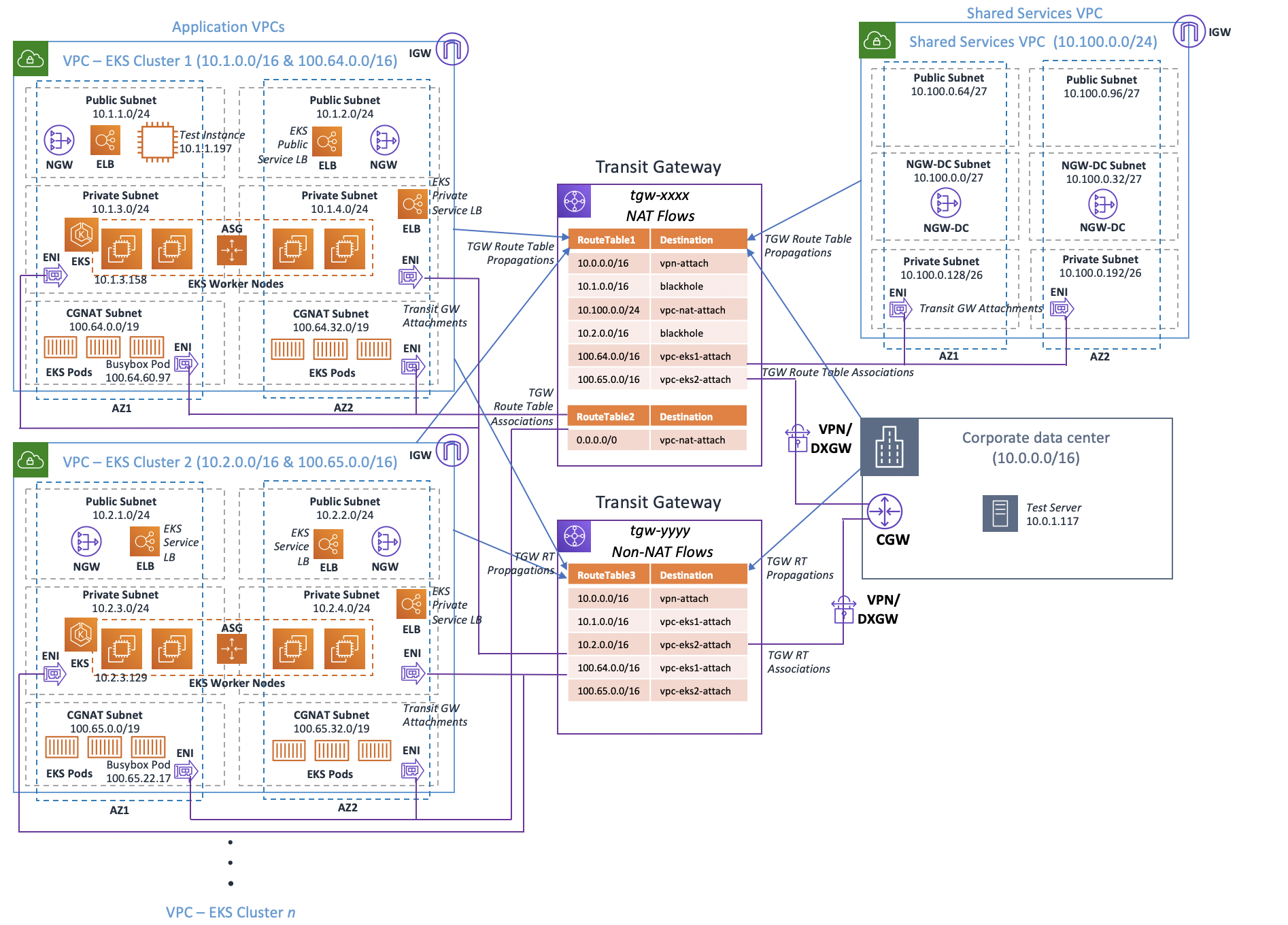
Figure 1 – End to end architecture
The diagram shows two EKS clusters, as per best practice recommendations we allocated a dedicated VPC per EKS cluster, these clusters can be delivered in the same AWS accounts or across AWS accounts. The AWS Transit Gateway recent support for inter-region peering increases the flexibility of the VPC connectivity model, which now allows for connectivity of VPCs that span across regions, in our example above we are only utilizing one region. The pods (pod IP addresses are delivered via secondary ENIs of the worker nodes) are hosted in dedicated subnets (CGNAT Subnet) using RFC6598 addressing (the procedure to enable this in your EKS clusters is documented in the earlier referenced blog). The EKS worker nodes are provisioned in the Private Subnet. We are deploying internal elastic load balancers in the same subnet to function as the load balancer for EKS Services. We are using two TGWs to serve: NAT flows (flow 1 listed above) and non-NAT flows (flows 2–4 listed above). We chose to use a dedicated Shared Services VPC to serve as a central point of source NAT’ing across all EKS clusters. Customers often will use a Shared Services VPC for services shared across the enterprise such as NAT, proxies, VPN, authentication systems, and various other security and management tools. Finally, we provide connectivity to a corporate data center via VPN in our example. However, this could also be performed using a Direct Connect via an AWS Direct Connect gateway (DXGW) that has an association with the Transit Gateways.
Pod to data center connectivity pattern
The transit gateway enables customers to connect their Amazon Virtual Private Clouds (VPCs) and their on-premises networks to a single gateway in a scalable manner. The transit gateway can support VPCs that span multiple AWS accounts if your enterprise delivers applications that span a multi-account environment. We are leveraging two TGWs to address all of our various flows, in particular those flows requiring NAT (pod to data center connectivity) would traverse the top transit gateway (tgw-xxxx), those flows without a NAT requirement (data center to EKS Service, pod to pod, and pod to EKS Service flows) will leverage the bottom transit gateway (tgw-yyyy).
The primary reason for introducing NAT is to avoid advertising the RFC6598 (ie 100.64.0.0/10) address space into your data center. To support pod connectivity into an enterprise data center in this design requires either advertising the RFC6598 addresses into the corporate DC or leveraging source NAT to hide the pod addresses.
We are using two route tables in the NAT transit gateway (tgw-xxxx) to facilitate routing all traffic to the Shared Services VPC (RouteTable2 in Figure-1) and back from the Shared Services VPC to the data center (RouteTable1 in Figure-1). The other flows not requiring NAT would leverage the bottom transit gateway (tgw-yyyy in Figure-1).
It should be noted that the default behavior of EKS is to source NAT pod traffic to the primary IP address of the hosting worker node. We will disable this behavior and configure EKS to deliver the pod traffic without NAT allowing us to configure the source NAT function externally (in our case the Shared Services VPC NAT GW). This enables direct inbound communications to pods as well without causing asymmetric flows. An added benefit with this approach is providing full visibility of the pod addresses with tools such as VPC Flow Logs, VPC Traffic Mirroring, and 3rd party monitoring tools.
Packet flow walkthroughs
Let’s walk through two of the flows we discussed earlier and demonstrate how they are routed using the TGWs in our architecture, in particular we will show:
- Pod to data center private connectivity flow
- Data center (or corporate user) to EKS service connectivity flow
Pod to data center flow walkthrough

Figure 2 – Pod to datacenter flow
For our first flow, let’s take an example of a pod in the Applications VPC with an IP address of 100.64.60.97 that wants to communicate with a web service in the data center with an address of 10.0.1.117. Pod traffic destined for data center services is first routed through the Shared Services VPC where it is source NATed to the NAT GW private IP (10.100.0.11 in this example). The typical behavior of the NAT GW is to source NAT to the internet to provide external communications. In our case, we are source NATing to the private IP address of the NAT GW and routing the traffic back to the Transit GW in order to use an address that is routable within data center. Let’s illustrate this via a packet walk.:
- The pod (100.64.60.97) initiates traffic destined to a web service (10.0.1.117) located in the data center. The packet leaves the pod and is delivered to one of the secondary ENIs on the EKS worker node. Since we are leveraging CNI custom networking, the traffic is routed to the subnet we defined in the ENIConfig custom resource. In our case, we are using the CGNAT subnet (100.64.x.x) so we consult the routing table for those subnets for next hop information. We select the data center route (10.0.0.0/16) destined for the transit gateway (tgw-xxxx depicted earlier) as our next hop. The traffic enters the transit gateway via the Transit GW attachment (located in the CGNAT subnets) and uses the transit gateway routing table (RouteTable2) that is associated with our Application VPC attachment. In our case, the routing table has a single default route (0.0.0.0/0) directing all traffic to the Shared Services VPC.
- Next, the traffic enters the Private Subnet of the Shared Services VPC (because the Transit GW attachments are in those subnets). The traffic is subject to the VPC routing table for the Private Subnet, which routes all traffic (0.0.0.0/0) to the NAT GWs (in our design we have deployed multiple NAT GWs across two Availability Zones for high availability and load distribution). The packet next traverses the NAT GW which source NATs the traffic from the pod address of 100.64.60.97 to the 10.100.0.11 private address of the NAT Gateway. Once the traffic egresses the NAT GW, it enters the NGW-DC subnet with a VPC route table that directs all the data center traffic (10.0.0.0/16) back to the NAT transit gateway.
- The traffic re-enters the transit gateway via the transit gateway attachments that reside in the private subnets of the NAT VPC. These attachments are associated with the route table (RouteTable1) that directs the traffic to the VPN connection (or Direct Connect gateway) destined to the data center.
- Finally, the traffic enters the data center and is delivered to the web server (10.0.1.117).
The return path for the traffic takes a similar path in the reverse direction.
Data center to EKS service flow walkthrough

Figure 3 – Datacenter to EKS Service flow
In the next flow, we will walk through a session initiating in the data center and connecting to a service hosted by EKS via private addressing. For this example, we’ll assume the IP addresses in the following table:

For this example, we’ll re-use the data center IP address of 10.0.1.117 for our client in the data center that wants to call our EKS service fronted by an Elastic Load Balancer that spans the Private Subnets in the Application VPC.
Let’s assume our environment has hybrid DNS resolution configured via a Private Hosted Zone in Route 53 and Route 53 Resolver Inbound Endpoint such that an EKS service has a DNS name of microservice.company.local (which is aliased to the ELB FQDN) and the client in our data center selects the 10.1.4.46 IP address. Note: If you want to share your private hosted zone across VPCs (for multiple EKS clusters and other AWS environments) that span AWS accounts please follow this procedure.
- Our client in the data center (10.0.1.117) makes the request to microservice.company.local, name resolution occurs and our workload issues the request to 10.1.4.46 (the client selected this destination IP but could have also chosen 10.1.3.195). The traffic enters the routing fabric in the corporate data center where it is ultimately forwarded to the Customer Gateway (customer gateway). The customer gateway is configured to forward the traffic (destined to 10.1.0.0/16) over the IPsec tunnel for VPN (or optionally the transit virtual interface for Direct Connect gateway to the Non-NAT transit gateway (tgw-yyyy).
- The traffic arrives at the transit gateway route table associated with the VPN or DXGW connection and consulted for next hop information. The most specific route is selected (10.1.0.0/16 in our case) which forwards the traffic to the elastic network interface in the private subnets of the Application VPC EKS Cluster.
- Next, the packet enters the private subnet of the EKS cluster where the route table is consulted and the local VPC route is selected (10.1.0.0/16). The traffic gets delivered to the ELB (10.1.4.46) where it is load balanced to the EKS worker nodes hosting the service. The traffic is forwarded to the EKS worker node instance port when the service was created. You can review the port chosen by describing your service as shown below. Finally, the traffic is delivered to the pod which constitutes the service.

Figure 4 – EKS Service port selection
The return traffic takes a similar path in reverse.
Additional Considerations
The design outlined above addresses the flow requirements by implementing two Transit GWs and a Shared Services NAT VPC. However, there are several alternatives and that can be considered if they better align to your particular requirements. For example, the RFC6598 address space could be advertised into the corporate data center, this eliminates the need to source NAT the traffic before forwarding to the data center. Network architects need to validate that the RFC6598 address space can be leveraged end-to-end in a corporate network before deciding on this approach.
Another option is to consider moving to IPv6 for your IP addressing, which removes the scarcity problem of IPv4 private IP address space since the public IPv6 space is so large. Enterprise customers who have not fully embraced IPv6 can consider this a longer-term option until it is more widely implemented.
EKS, by default, allows you to hide the pod address space leveraging the default behavior of the Amazon VPC CNI plugin for Kubernetes (EXTERNALSNAT=false). For small environments that don’t scale beyond a single cluster this solution might meet your needs thereby eliminating the need for a centralized NAT VPC. Direct pod source IP address visibility might be desirable however to allow operational tools like VPC Flow Logging and other tooling to aide in troubleshooting.
We have had many customers wish they had planned on allocating more IP addresses to AWS VPCs earlier in their journey. If you are in the process of designing a network with routable RFC1918 addresses in VPCs, then plan for the long term and don’t skimp out. Allocate the largest CIDR blocks you can support for your VPC, most customers eventually find that their AWS footprint is larger than their on-premises footprint so plan accordingly. In our design above we are adding an RFC6598 address block as the additional CIDR block, if you have routable RFC1918 addresses available, you could alternatively allocate those and avoid the complexities of setting up the NATing as described in this post.
Some of the flows we are introducing (pod to data center flows) require an additional pass through the transit gateway to facilitate source NATing, as a result there are pricing implications since the transit gateway charges for data processed (price per GB of data processed in us-east-1 is $.02, consult the pricing page for updated pricing for your region(s) of operation). For example, flows that go from EKS pods to the data center require transit gateway processing twice (once for processing traffic from the EKS VPC to Shared Service NAT VPC and again for Shares Services NAT VPC to data center processing). With this flow the transit gateway data processing fees are effectively doubled, if you are egressing a significant amount of traffic you might consider implementing a distributed NAT solution across all EKS clusters, this eliminates one of the processing flows to reduce that cost at the expense of a NAT GW(s) per VPC. You need to determine what’s most cost effective for you based on your traffic patterns and management requirements.
Finally, in our architecture described, we have internet egress for pod traffic that uses a NAT GW in the local Application VPC where the EKS cluster is. Alternatively, outbound internet access could be centralized in the Shared Services VPC. To enable this, modify the default route in the CGNAT Subnet (the pod subnet) route table to point to the NAT transit gateway, which routes internet traffic via the NAT GWs in the Shared Services VPC.
Conclusion
As customers increasingly move to EKS and containers, they are looking to introduce them in a minimally disruptive way to their existing AWS environments. We demonstrated how you can preserve your RFC1918 address space by expanding your available VPC IP addresses into the RFC6598 space while still enabling traffic flows between them. We leveraged the Transit Gateway to help create scalable and repeatable patterns in the process to scale and support your entire enterprise needs.
Additional detail for Network Architects
Let’s walk through the configuration details for the environment to give you an idea how you can implement in your own environment. We’ll start with a detailed diagram including the routing tables for all the subnets in our VPCs.
Detailed Architecture Diagram (with routing tables)

VPC configurations
EKS-Cluster 1 VPC

EKS-Cluster 2 VPC

Shared Services VPC

Route Tables
The route tables for the environment are shown below.
EKS-Cluster-1 Public Subnet

EKS-Cluster-1 Private Subnet

EKS-Cluster-1 CGNAT Subnet

EKS-Cluster-2 Public Subnet

EKS-Cluster-2 Private Subnet

EKS-Cluster-2 CGNAT Subnet

Shared Services VPC NGW-DC Subnet

NAT VPC Private Subnet

Security groups
The security group configuration for the EKS worker nodes needs to be adapted to allow whatever flows you would like to support. For example, if you would like to allow communication from pod to pod across clusters be sure to allow inbound connectivity into the destination EKS worker node security group allowing the appropriate pod source addresses and protocol/port.
Transit Gateway configurations
NAT Transit GW – RouteTable1 Associations

NAT Transit GW – RouteTable1 Propagations

NAT Transit GW – RouteTable1 Routes

NAT Transit GW – RouteTable2 Associations

NAT Transit GW – RouteTable2 Propagations

NAT Transit GW – RouteTable2 Routes

Connectivity demonstration
We can demonstrate connecting to one of our EKS pods and validating connectivity with a web server in our data center as follows.

Next, lets validate pod to pod connectivity across EKS clusters.

Let’s check data center consumer to EKS Service connectivity:

Finally, let’s look at pod connectivity to an EKS Service across EKS clusters:
